Showing posts with label John Roebling. Show all posts

24 June 2017

GTR 1873 Changing the Gauge


Before every engine trots the ghost of a superseded horse.
H.G. Wells

The idea for this post originated from an interesting three-page document from archive.org summarizing the process used during the Grand Trunk's conversion of its single-tracked main line to Standard Gauge. However, when one starts researching, many more interesting tangents develop and a five-image post turns into a somewhat longer effort.

In hindsight, many things could have been done differently to avoid the series of financial errors and assorted disasters which culminated in the final bankruptcy of the Grand Trunk Railway.

Rail enthusiasts generally have an overriding interest in motive power. I have included a few photos of mid-1800s GTR power to evoke 'the era'. Imagine how 'cutting edge' this technology was back in the stage coach, sailing ship and early steamship era. By the same token, one can imagine all the capacity and reliability limits the railway pioneers were facing with their early motive power, only 20 years into Canada's railway era.

Considering the dominant land transportation of the day - horses dragging a vehicle on various high-friction and undulating roads - the railway was soon to become 'a magic carpet made of steel'. In Canada, some technical refinement was necessary before this could become reality. 

As you already know, the other side of 'low friction' is 'low adhesion' - the railway right-of-way had to be professionally engineered to limit grades. As you also already know, Canada's earliest railways were built mainly with human and animal muscle power and primitive explosives. 

Building a reasonable Rail Way was expensive enough ... without having to rebuild it because of technological problems or errors. And without kleptocratic opportunists siphoning off 'mobile, sensitive and scarce' capital to line their own pockets ... during the early phases of raising capital ... and during construction.


from: The Science of Railways; Marshall M Kirkman; 1894-1908; World Railway Publishing Co.

Convenience, necessity and imperial hubris combined to cause Canadian railway builders to assume that British rail technology was appropriate for use in Canadian conditions. Before mass production made steel rails of today's profile cheap, iron rails of British design were imported. Unbalanced wheels, on British-style rigid-framed equipment, pounding on brittle iron, on very cold Canadian winter days ... caused a very high rail failure rate.

The following passages come from:

Canada and the Grand Trunk, 1829-1924; HA Lovett; from archive.org

On Page 51, regarding the GTR construction in June 1860 ...


A decade later, coming from the position of Chairman of the Great Western Railway (the English GWR), Richard Potter 1817-1892, a British lawyer and businessman became Grand Trunk President from 1869 until 1876. He studied and then dealt decisively with a number of issues - financial and practical - which needed resolving. He received little thanks for his efforts.


A Canadian 'innovation' - Provincial Gauge - had cost the GTR a lot of money.

*  *  *

Here is Canada's railway network in 1860.

from: The Railway Builders; Oscar D Skelton; 1916; Glasgow, Brook & Co.
It is striking how the 1860 railway network is almost exclusively used to link bodies of water - the 'portage railways' were becoming longer and longer. An exception to this is the Grand Trunk - which parallels the St Lawrence River. 

One Canadian writer of the period suggested that British canals were little more than enlarged ditches compared to the waterways of Canada. For early Canadian bulk commodities for export ... such as timber and grains ... railways operating in competition with water had no hope of competing on capacity or price with natural waterways and/or canals. The period of the winter waterway freeze-up simply could not compensate for the railways' limited haulage capacity and relatively high operating costs.

*  *  *

The Debate About Gauge
from: GWR Company Servants; Janet KL Russell; 1983; Wild Swan Publications.
If you have ever watched YouTube videos showing Russian railways (with a gauge of 1520 mm - almost 5 feet) or Indian railways (1676 mm - 5.5 feet) it is easy to see that our Standard Gauge often leaves something to be desired with the potential to run today's best high capacity locomotives and rolling stock. 

It would not have been possible to finance many of North America's railways if the system had used a broader gauge in the 1800s. The extra initial cost of wider rock cuts and fills, more substantial bridges, heavier rail and more powerful motive power would have made many wilderness railway lines unaffordable. But ... perhaps this might have been a good thing ... as the Canadian network of the early 1900s would not have been as overbuilt as a result.

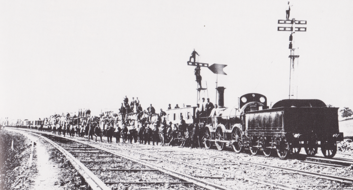
An extreme case of broad gauge (above) is the Great Western Railway of England - also known as God's Wonderful Railway. Here, its 7-foot gauge is being converted to Standard Gauge in May 1872. The line involved was from Gloucester to South Wales - about 500 miles of track, including double track and sidings which were all converted in that operation. 

*  *  *

Canada's Great Western Railway in 1860

from: Canadian Railways in Pictures; Robert F Legget; 1977; Douglas and McIntyre.
Here is the Great Western Railway of Canada at Paris Jct in 1860.
The Great Western converted to Standard Gauge between 1870 and 1873.
It was absorbed by the Grand Trunk in 1882.

The stub in the foreground seems to be broader.
Notice the turntable at the left, possibly with stock cars nearby.
There are raised switch targets/lamps.
The switchtender's cabin may be equipped with a telegraph.
The engineer stands at ground level with his oil can.
Of course, the fuel is wood and the locomotive has many interesting details.

For a post dealing primarily with Canadian track hardware and gauge before 1870 ...
it was extremely difficult to find any photographs displaying typical track structure well.
... Particularly of the Grand Trunk before conversion to Standard Gauge.

*  *  *

from: Railways; C Hamilton Ellis; 1974; Hulton Press.
Here (not dated) is John Roebling's railway suspension bridge near Niagara Falls ...
preserved in the station name Suspension Bridge.

In many cases, trains were pulled across by a special lightweight Great Western locomotive ...
which I think is shown here.

The gauges supported here are:
Standard Gauge - 4 ft, 8 1/2 inches.
Provincial Gauge - 5 feet, 6 inches.
Erie - 6 feet.

*  *  *

The Grand Trunk

from: Railroad History - 147, Autumn 1982; The Railway & Locomotive Historical Society. via Railfare. Omer Lavallee, Raymond Corley.
Here are three Grand Trunk locomotive photos - two before regauging and one after. They come from a particularly interesting edition of the publication noted. Omer Lavallee provided an overall corporate history of the Grand Trunk's development and its subsidiaries. Raymond Corley discussed motive power acquisitions ... and he and William Edson provided a full list of all Grand Trunk power - through its five renumberings.

The text notes that the Spitfire - 41, was built by Fairbairn as a 2-4-0 in 1855 and converted to a 4-4-0 circa 1860. It was scrapped in 1871.

from: Railroad History - 147, Autumn 1982; The Railway & Locomotive Historical Society. via Railfare. Omer Lavallee, Raymond Corley.
The Trevithick - 209 was the first locomotive built at the GTR's own shops at Point St Charles in May 1859. It was off the roster by 1874. It was the only locomotive of its class and speculation is that it is the namesake of the gentleman by the first driver. This photo is a favourite of CNR histories and generic railway history 'books by the pound'.

Dana William Ashdown has a very nice photo of 209's construction on page 29 of Iron & Steam; 1999; Robin Brass Studio.

These two Provincial Gauge locomotives participated in the regauging activities, and you'll find their numbers in the project document near the end of this post.

*  *  *

GTR After Regauging

from: Railroad History - 147, Autumn 1982; The Railway & Locomotive Historical Society. via Railfare. Omer Lavallee, Raymond Corley.
Standard Gauge GTR power is the Portland 1873 product, Eng 377.
The fuel is now coal (with wood kindling) and the track hardware is what you'd expect.


*  *  *

This Coles reprint provides interesting contemporary railway gauge details and debate.

... so many theories ... so many opinions ...
At the very end, watch for John A Macdonald's participation in the Provincial Gauge error.


*  *  *

This commentary on track gauge comes from civil engineer Thomas Coltrin Keefer's (1821-1915) essay Travel and Transportation - originally published in 1863. TC Keefer sited (apparently without much credit) the Victoria Bridge. He almost participated in the Grand Trunk Railway project and was frustrated in his life-long desire to lay out a Canadian railway. His single most notable engineering project was the design of Montreal's civic waterworks. He had a broad range of transportation, economics and engineering interests and writings.

from: Philosophy of Railroads; TC Keefer (ed. HV Nelles); 1972; University of Toronto.

from: Philosophy of Railroads; TC Keefer (ed. HV Nelles); 1972; University of Toronto.

*  *  *

Map of the Grand Trunk and Its Gauges

... Showing the full scope of GTW's gauge issue, particularly as it consolidated smaller lines.
This is Lavallee's map from the same source as the Spitfire and Trevithick photos.
The map was printed across the gutter of the book.
from: Railroad History - 147, Autumn 1982; The Railway & Locomotive Historical Society. via Railfare. Omer Lavallee, Raymond Corley.

*  *  *

This is how they organized the change of gauge ...


Above: Eng 68 and 212 are the numbers added.


In advance of the change of gauge, this advertisement was placed.


from: Railways of Canada; Nick and Helma Mika; 1972; McGraw-Hill Ryerson.
*  *  *

Sacred to the memory of those of us with links to the region ... was the last bastion of Provincial Gauge. This was the insular, 12 mile, portage railway, the Carillon and Grenville. Its Birkenhead, Canada Works, engine began its career with the Grand Trunk and operated on the C&G from about 1870 until 1910. Here it is passing over a stub switch.

from: Canadian Railways in Pictures; Robert F Legget; 1977; Douglas and McIntyre.

*  *  *

As old as the Grand Trunk locomotive Trevithick is this illustrated guide 
which my great-grandfather purchased secondhand. 

The first image includes Roebling's suspension bridge at Niagara Falls.

WS Hunter's Panoramic Guide from Niagara to Quebec; c1858; Collection of JHS Parke.

*  *  *

The second pair of images shows the layout of canals and railways around Montreal.
The new single-tracked Grand Trunk Railway can be seen.

(As usual, the larger image was cut to work around the Google algorithm size limits.)

WS Hunter's Panoramic Guide from Niagara to Quebec; c1858; Collection of JHS Parke.

WS Hunter's Panoramic Guide from Niagara to Quebec; c1858; Collection of JHS Parke.

03 July 2015

The Telegraph, Part 3

On the CPR, somewhere in British Columbia in 1887..

CPR station telegraph office 1887

Here is a quick overview of a Canadian wilderness telegraph office. Interior photographs of train order offices of this era are unfortunately rare, partly because of the difficulties of getting the exposure right.

I have labelled some interesting features. To work, one must make a mess ... so this scene is nicely tidied and posed. The Queen Insurance hanging is probably a useful large format calendar. You can see quite a few bits of telegraph equipment tucked in corners of the desk and the shelves above it - probably several spares. Where did you get those curtains? It is not possible to see a telegraph key, but it should be to the right of the train order forms.

It is possible that above the 'T' in 'Telegraph key' is a bottle of acid with the local circuit battery behind it ... but the battery cell(s) may actually be elsewhere. The fact that working telegraph equipment, its power, and complete spare components could fit on the back of one desk illustrates the elegance and simplicity of the technology used on the early railways in Canada and the US.

*  *  *

For the sake of illustration, I believe this is the 
actual working telegraph equipment of this train order office.


Telegraph switchboard, sounder, relay: The switchboard allows various configurations of the equipment. Using it, the office can be shut down, or the equipment can be protected from lightning. The station's equipment can be connected to, or taken off, the main line. Various configurations can be set up to help linemen test for telegraph line faults or breaks. Little metal pegs are inserted in the holes make the connections between two conductors. The instrument wires come off at the '8 o'clock' position of the switchboard.

The wall-mounted, pivoting coal oil or kerosene lamp provides light for clerical work at night.

The telegraph relay (to over-simplify) is an electromagnetic audio 'amplifier' of the main line current.

The telegraph sounder produces the sounds which the telegraph operator decodes as letters and numbers. Generally, experienced operators recognized the 'sound of a letter' ... instead of 'hearing' and counting up the clicks and clacks of the sounder as a message was being received.

As the operator must perform certain duties outside (such as delivering orders to passing trains or setting the train order signal) placing the sounder on the window sill ensures he will hear and be able to respond to any railway messages requiring his immediate response while out on the station platform.

The telegraph key and the local battery are the two pieces of equipment not shown.

This simple communication equipment described is well-suited for receiving the precise time ... relayed from an observatory at McGill University, Montreal; or from the Dominion Observatory in Ottawa. The equipment can be used to relay train orders from the dispatcher (located at large settlement 5 to 200 miles away) governing the movement of passing trains. When the operator and equipment are not busy with railway business ... local people or travellers can have the operator send and receive personal, commercial, or official information for them ... for a fee, of course.

Unlike some European railway telegraph equipment, this equipment requires the operator to be proficient in receiving Morse code by ear and he must be capable of sending with accuracy and speed. The equipment is cheap enough that spares are available in quantity. Replacing equipment is done quickly and easily ... by loosening or tightening the thumb screws which secure the conducting wires.

That was the All-Canadian, Canadian Pacific Railway in 1887 - shortly after it was completed.

*  *  *

Three decades earlier in eastern Canada ...

Cover, Grand Trunk Railway Rules of the Telegraph Department


The glosses for each rule are italicized and I am reproducing most of the wide variety of text styles used for emphasis.

REPORTING TRAINS
[GRAND TRUNK TELEGRAPH RULES]

Reports to be furnished by station-masters.
24. Reports of the departure of trains must be written out in full, and signed by the Station-master, the original copy to be kept in the custody of the Operator.

Up trains.
25. When an up-train is to be reported, the Operator will TWICE call "U.X." THREE TIMES, signing BOTH times, and then proceed with the report.

Down trains.
26. For down trains, the call "D.X." is to be used instead of "U.X.", in the same manner.

Reports of trains.
27. When the calls "D.X." or "U.X." are heard on the line, each Operator will take the report that follows, and deliver it to the Station-master without fail. At head quarters the Operator will deliver it to the Superintendent of the road.

Night reports of trains.
28. Reports of trains must be sent as quickly as possible after receipt, and during the night must be answered by all the NIGHT OPERATORS by "O.K." and signature.

*  *  *
Discussion ...

Someone recently referring to 'correct historical dialogue' in a movie said that NO ONE said 'O.K.' in conversation until after World War 2. ... But ... every town had a telegraph operator and many teenage boys of the time either aspired to become locomotive engineers or hung around the local station learning Morse.

As you can see from the 1867 map below, by the time of Canadian Confederation the Grand Trunk Railway ran from Riviere du Loup, Quebec and Portland, Maine in the east ... through Montreal ... to Buffalo, New York ... to Goderich, Ontario and Detroit, Michigan in the west, with its goal being Chicago. It also had steamers from Sarnia to Chicago.

In Britain, 'up trains' often referred to those travelling TO LONDON. The Grand Trunk was a British corporation with its president in London, England and they hadn't yet adopted the North American 'rulebook standard' of either east-west OR north-south for every single line. I have discovered that travelling south-east to Portland on the Atlantic was 'DOWN' in 1857 ... so who knows whether UP/DOWN was standardized over the entire system or by individual division.

Long before national time zones, the railway in 1868 had its schedule times 'standardized' as being one of the local solar times of the following cities: Portland, Montreal, Toronto, or Chicago. Montreal (Canadian headquarters) time applied to eastern Canadian lines as far west as Toronto.

This public directory map purposely shows the Grand Trunk Empire well beyond Canada's borders as this multinational corporation was designed to pay significant regular dividends to its British investors by drawing as much eastern North American traffic as it could.

Map Grand Trunk Railway system 1867

The Grand Trunk Railway in 1867 ... before asphalt, electricity, and the Canadian Pacific Railway.

*  *  *

SIGNALS
[GRAND TRUNK TELEGRAPH RULES]

Signal "23".
29. The signal "23" intimates that a message for ALL the stations is to follow.

General call X.
30 When a circular or "23" message is to be sent, "X" will be used as a GENERAL CALL, and all the offices are to answer to it, commencing with the most distant. The same order must be observed in acknowledging the message by "O.K." and signing.

Circulars to be filed.
31. All circulars and "23" communications must be carefully filed, and kept in the office for reference.

Signal "17"
32. The signal "17" called by an office, signifies a communication requiring GREAT HASTE and of the UTMOST importance. When used ALL other offices must CEASE WORKING, and close circuit until the communication is sent and ACKNOWLEDGED.

Signal "17" to be used only in emergencies.
33. Operators are forbidden to make use of signal "17" excepting for the purpose of stopping or dispatching a train - preventing an accident, or for some other object of undoubted importance.

*  *  *
Discussion ...

As you are no doubt inferring, the railway telegraph is a big 'party line'. (For younger readers ... back in the olden days {1950s, etc.} before modern digital telephone switching and private lines ... multiple telephones  were wired to the same circuit ... and different bell 'rings' were used to alert an individual subscriber that a call was for them. Once the phone was answered, any busybody wired on the same party line could quietly lift their telephone receiver and listen in to the conversation. So telephone party lines could be like involuntary conference calls if the others wanted to eavesdrop.)

Telephone 'party lines' existed because it was the cheapest way for most people to get phone service. Railway station telegraphs all wired on the same circuit was also the cheapest way to wire up telegraphs.

However, in addition ... on the railway ... the 'railway party line' provided an early version of the e-mail 'mailing list' and ensured all telegraph operators had the ability to overhear and correct mistakes made by other operators which might have caused accidents.

Generally 'office signals' were telegraphed to call a particular station(s) on the 'party line' for a message specific to them.

Examples circa 1960 : 
  • Montreal Central Station = KN
  • Montreal Yard = MY
  • Garneau Yard = JU
  • Joffre = JF
  • St. Hyacinthe = SY

In 1855 two particular numbers 17 and 23 indicated special messages ...
  • Hearing the sound of one meant  URGENT PRIORITY ... 17
  • Hearing the other meant  MESSAGE@ALL ... 23


The Grand Trunk listed 33 of these two-numeral codes in their 1855 telegraph rulebook to 'save bandwidth' and avoid misunderstandings for common messages.

Other examples ...
  • 1 = Wait a moment.
  • 2 = What time is it?
  • 6 = I am ready - proceed.
  • 21 = I am going out to deliver a message.
*  *  *

Montreal harbour and Victoria Bridge construction 1859

To give you an idea of Canadian technology in Canada's largest city then ...

Here is the Montreal Harbour in 1859 as the Victoria Bridge of the Grand Trunk Railway is being completed to the south shore of the St. Lawrence River. Until this time, the only way across the St. Lawrence was by ferry ... or on the ice. In the harbour is one large steam-powered ship and a few small paddle-wheelers ... and everything else is sail and horse power.

In 1867, a Grand Trunk express train could get you from Montreal to Toronto (333 miles) in 18 hours. The 515 miles from Toronto to Chicago would be covered in 22 hours ... after changing to the Michigan Central at Detroit.

*  *  *

MAIN BATTERIES
[GRAND TRUNK TELEGRAPH RULES]

Batteries
34. Main Batteries must be kept constantly clean and bright. The holes in the leaders must be kept always clean, as also the ends of the wires which enter them.

Battery supplies.
35. Battery supplies will be furnished on application to the Superintendent. Operators in charge of stations must see that great care is exercised in the use of these supplies, (particularly mercury, nitric acid, and platina) and that there is always a sufficient quantity on hand.

Night batteries.
36. Where GROVE'S batteries are used, and kept on night and day, they must be carefully cleaned once a-day, at an hour when they may be most conveniently spared.

Main batteries on Sundays.
57. Main batteries must be kept on during Sundays, although on that day the line will be closed, excepting in cases of emergency.

*  *  *

Discussion ...

So now we are getting into North American railway telegraph technology ...

Remember (on the post 'Telegraph, Part 1') that in 1837 Steinheil in Germany had accidentally invented the 'earth return' or 'ground return' when he was trying to use two railway rails to act as his telegraph circuit ? ... This was significant because it meant getting a telegraph signal from point X to point Y only required one wire as long as both ends of that wire were grounded to earth.

Using a water metaphor is more intuitive when explaining electricity ... but it only goes so far ...

If B was a water pump - instead of a battery - and 'X to Y' was a water pipe placed into the ocean on both (ground) ends ... water could easily be pumped from X to Y and the ocean would restore its normal level between Y and X ... But we wouldn't expect the particular water molecules which had been pumped X to Y to migrate back 'home'.

So messages move along our single telegraph wire by battery power (pressure or 'potential') in the line ... as long as the line is properly insulated against current loss all along the way ... and as long as the battery is strong enough to send the current (potential) as far as we want it to go.

But  ... a gutless water pump and a leaky water pipe couldn't move much water from X to Y.

Sketch of main telegraph circuit

As railways generally operate between large terminals (e.g. Montreal and Toronto) with smaller stations along the route (e.g. Cornwall, Prescott Junction, Kingston, Cobourg) ... the local stations had simple local systems (as seen in the CPR station photo at the top of this page) and left the literally 'high-powered technology' for the main terminals. 

More about this and pumping messages 'backwards' Y to X in Telegraph 4 ...

*  *  *

Hardware of the times ...

Birkenhead locomotive Great Western Railway

Being a British company, the Grand Trunk Railway began with 56 locomotives built at Birkenhead, England from 1854 to 1858. This firm also built 4 of the same type for the Great Western Railway of Canada (shown) which was later absorbed by the Grand Trunk.

By 1860, these wood-burning locomotives were rebuilt to meet the demands of Canadian service as much as possible. In particular, this photo (circa 1870) shows the addition of two more pilot wheels (total 4) to reduce derailments on the rougher North American track. After starting up, the Grand Trunk wisely curtailed its un-American activities and purchased Canadian and American locomotives.

John Roebling's suspension bridge, Niagara Falls

John Augustus Roebling (1806-1869) was a German-born bridge engineer. He eventually came to America because he wanted to follow his dream to build suspension bridges. The Prussians, for whom he had been working, didn't need no steenkin' suspension bridges. So in America he eventually had the chance to build the longest railway bridge in the world (at that time) and the world's first railway suspension bridge - over the Niagara Gorge. 

For safety, he wanted to keep horses away from iron horses. So pedestrians, carriages and wagons had a separate deck below the railway level and it was enclosed so horses could not panic and hop over the side. The supporting trusses of the lower level also gave the bridge extra rigidity to better support railway traffic. Railway suspension bridges are not common and you can imagine why. Roebling also concluded that 2 large cables supporting each level would provide more stability that many smaller cables. So the bridge has just 4 main cables supporting it.

Construction began on the bridge in 1851, and the bridge opened in March 1855 and was used for another 40 years. Trains crossed at about 5 mph ... so it must have taken about 10 minutes for a train to get across - giving passengers a good long look out ... and down. 

Groups of people crossing (e.g. military) were prohibited from marching in step. Bands could not play as they crossed the bridge unless they rode in a wagon. No more than 60 cattle were allowed on the bridge at any one time ... divided into groups of 20 ... each with its own drover to keep them from charging off if a locomotive ran over head.

At least we can still marvel that they built such a thing back in the 1850s.

Because of Canadian government subsidy and bond guarantee legislation, the Great Western ... like the Grand Trunk ... originally operated with a 5 foot 6 inch gauge. Two other railways used the bridge as well ... the New York Central with today's standard gauge of 4 feet 8 1/2 inches ... and the Canandaigua & Niagara Falls with a 6 foot gauge.

Four rails were necessary on the railway deck to handle the traffic from these railways. In the photo below, three of the rails have recently been used - broad-gauge locomotives sometimes pulled standard gauge cars. This made things interesting for the switchmen when the time came. You can see the four main cables coming down from the support towers. It was in this era that the first telegraphs were used.

John Roebling's suspension bridge at Niagara Falls