Showing posts with label telegraph. Show all posts

03 November 2015

Portage 1985 - Fifth Section


The 5221 has just switched out that blue hi-cube boxcar for CP.


The 5221 is back on the train and ready to leave town.


This photo of the extra 5557 west is included mainly because of the diminutive boxcar behind the power.
Even compared to standard 40 foot boxcars farther back in the consist, it looks small. 
The elevator here holds chemical fertilizer.


Prairie sentinels, version 1.0 at Third Street.


Extra 5903 west with 4202.
MLW (Alco-style) power was rare west of Winnipeg on CP.
I'm not sure, but I think the raw power of the 4202's prime mover has blown its motor compartment doors open!

*  *  *

A Trip to the Manitoba Agricultural Museum 
at Austin, Manitoba


This Manitoba Wheat Pool sign on the Austin museum elevator shows the ingenious design techniques used in country elevators and it shows this Austin elevator in particular. Before rural electrification, grain was weighed, graded and shipped from country elevators whose only power came from a small internal combustion engine. To avoid grain dust explosions, the internal combustion engine was generally kept in a separate external building with the power coming into the elevator via a belt.

Early in the era of western settlement, milling companies also owned elevators to ensure a steady supply of grain of a known quality ... and probably to make money by controlling supply costs.

The grain started every transfer process in the pit. An endless belt of buckets (the elevator 'leg') gave the grain potential energy as it reached the top of the elevator - the cupola.

Lifted into the elevator's cupola, the 'gerber' was the location where a route for the grain was switched and set ... and gravity did the rest to drop the grain into a storage bin, onto a shipping scale or into a boxcar.

After it was received and weighed, graded and stored ... the grain might make several more trips into the pit and up the leg as it was re-sorted into different bins, or weighed and shipped.


A typical early grain wagon is positioned for tipping into the grain pit.
Gross and tare weights of the wagon were used to calculate the weight of grain delivered.
I have boosted the resolution of the bin numbering diagram to the right of the wagon -
the diagram shows the relative location and capacity of the bins.
In this elevator, the chutes are wooden.
Grain can also be loaded into wagons on the elevator floor.


Here is a photo of the shipping scale mentioned in the diagram.
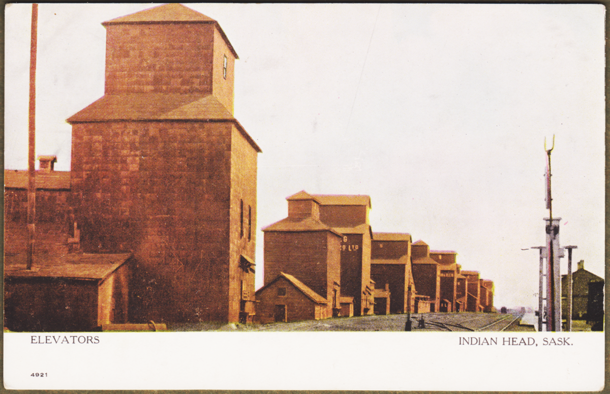

Unused postcard. c1900?
The non-standardized design of early grain elevators can be seen.

The elevators with larger cupolas offered more space for equipment and its maintenance - particularly for the top axle of the leg ... and the gerber from which the grain was directed into different chutes. The Austin elevator dates from 1905 and it does not have one of the 'modern' full width cupolas, eg. as seen on the 'modern' third elevator from the camera.

The CPR station is seen across from the elevators. The device in the right foreground is a main track switch lined for the main track. It's top fitting allows for an oil switch lamp to be mounted at night - by climbing the ladder on the far side - to indicate the switch's alignment to distant, approaching trains.

*  *  *

After Posting ...

from archive.org - research by Jim Christie

After I completed this posting, Jim Christie found this excellent journal article about 1917 elevator design. I haven't been able to resolve the smaller text on the illustration, but you'll find a lot of elaboration on elevator design and operation in the article itself.


*  *  *


The station building at Austin is the former Northern Pacific Railway station from Baldur, Manitoba - about 65 km SSW of Austin.


Inside the station we found a nice collection of equipment.
The telegraph switchboard is seen - explained here (Telegraph - Part 6) .
Beyond it are the two black handles for the train order signal.
As a bonus, there is one CP train order hoop on the wall,
and below are two CNR hoop assemblies (V-shaped).


This wooden CPR boxcar was built by Canadian Car and Foundry in 1914. While train air brakes had previously replaced manually-applied brakes on each car by roof-running brakemen ... the roof walk would still be used by crew members while switching - to relay signals to the engine from the worker throwing switches and coupling cars at ground level.

If a brakeman was riding a car 'kicked' down a track by a locomotive, this primitive hand brake would have required a lot of force (and time, and probably a wooden club for leverage) to get the chain tightened ...  you can see the chain winding at the bottom of the hand brake shaft. In contrast, modern hand brakes were quicker to apply and had a greater mechanical advantage to stop the kicked car with greater control.

You can also see the old arch bar trucks, and of course, the plain bearing journal boxes.

There is another interesting feature - a poling pocket. This is the raised metal 'cup' above the foot iron at the end of the car. If a crew needed to move a car on an adjacent track (to which the engine could not couple) a stout pole could be placed into one of the locomotive poling pockets and into the car's poling pocket. This dangerous procedure became illegal as the pole could slip or break, killing or badly injuring nearby crew members. 

from: Canada, A Geographical Interpretation; Ed: John Warkentin; 1967; Methuen.
Consider the small capacity of the horse-drawn grain wagon (above) photographed on the Austin elevator floor ... and how long it would take to move a year's harvest to a nearby elevator over dirt roads.

As the Prairies were settled, more and more railway branch lines (map above) were built so that farmers were no more than 10 miles from an elevator. In the 1980s and 1990s, with farmers using large trucks and paved roads, a great deal of the original branchline network was declared surplus and torn up.


A long-eared rabbit is making a move at Third Street.


Sophisticated photographers refer to 'The Golden Hours' - the period when the sun is near the horizon, refracting a more golden light and beautifully illuminating, let's say, a child playing with a drinking fountain. 

However, if there is an opposite to Gold, it can be found when one is forced to shoot into that golden light - as seen above. In the summer evening, the CN extra 4609 east is rolling into the siding at Portage, probably from the Gladstone Sub. The 'oddly painted' unit leading is formerly of the Northern Alberta Railway - it was jointly owned by CP and CN.


We may have been 'rolling' with my uncle driving, as I was able to take this photo with under less difficult conditions.


Compare and contrast ...

Here is a modern metal-clad wooden elevator.
... powered by electricity,
... using electronic sensors and microprocessors (not beam mechanical balances)
... to manage grain transfer and weighing.

Note the electric capstan and cable hauser for moving cars ...


What identical equipment is on both the Austin elevator and this one?
The arrow.

It shows the direction in which the track gradient descends ... downhill.
When train crews spot the grain cars, they are placed uphill -
so elevator workers can move them more easily for loading. 


The moving parts of the leg and the gerber are enclosed, but outside.


This is a natural gas pipeline pumping station.
The cylinders house pump turbines - which are spun by burning natural gas.


A CP intermodal westbound whistles, and thunders through the quiet prairie evening -
almost a century after the Last Spike.


05 July 2015

The Telegraph, Part 5

Local telegraph instruments & the local circuit ...

From a Canadian government atlas, here is a map with circa 1915 data.
Red represents telegraph lines.
Red dots represent telegraph stations.
... They kept track of these things back then.

Here are the CPR telegraph stations from Banff to Revelstoke.


Engraving of Field BC looking toward the 'east'.

Field, British Columbia at the bottom of the CPR's 'Big Hill'.
Travelling from right to left and up through the valley will eventually take you east to Calgary.

*  *  *

Running from east to west across the following map is the Calgary to Kamloops mainline of the CPR.

Lake Louise is 'Laggan'.
The original 'Big Hill' east of Field has recently been replaced by the Spiral Tunnels.
The Connaught Tunnel has not yet been built to avoid Rogers Pass.
Craigellachie, just west of Revelstoke, has a telegraph station.

Map CPR telegraph Calgary to Kamloops.

Mileages between locations, based on a 1892 timetable reprint :

Calgary - Field 133 miles
Field - Revelstoke 130 miles
Revelstoke - Kamloops 128 miles

This is just intended as an illustration of typical telegraph installations of the time. There is no way for me to know exactly what equipment was used circa 1900 ... but this area and map are interesting ... so it is being used as a 'model location' for this little essay. 

The telegraph 'main line' circuit runs Field to Revelstoke. The communications for the smooth operation of the railway and its other businesses depends on this through line working well. Some wires are probably dedicated to 'through traffic' ... others are for local train control and other messages. 

Large 'batteries' of cells are set up at Field and Revelstoke because they are large railway towns with extra resources and administrative staff to supervise operations. 

The cells may be gravity cells or perhaps lead-acid batteries are now in use. The gravity cells are 'primary' cells which react chemically to create their own electricity. The lead-acid cells are 'secondary' cells which must be recharged from a source of electricity ... such as a stationary steam engine-driven dynamo. The larger centres would get dynamos first, while intermediate stations would get along with kerosene for light, and gravity cells to operate the local telegraph circuit.

*  *  *

Sketch of Field to Revelstoke main telegraph line

Above is a 'model illustration' of a typical telegraph circuit of 100 miles or more.

When the Rogers Pass local telegraph instruments were not in use ... contacts 1 and 2 would be electrically bridged to provide continuity, Revelstoke to Field. This bridging would occur when no operator was on duty ... or if the Rogers Pass location was experiencing lightning ... to protect the local instruments from damage.

*  *  *
Simplified local station circuit and instruments.

These are the local instruments at the 'Rogers Pass' station ... another 'model illustration'.

In this simplified conceptual sketch you can see that the main line wires (solid lines) work  through the relay and key.

There is also a local circuit (dashed lines) working through the local battery, relay and sounder. Not included here is the essential switchboard and the 'ground' wire ... which we will get to in the next post.


*  *  *

This will explain almost everything ...

Telegraphs - the basic U-shaped electromagnet

This is the one 'magical' bit of information which explains just about everything you need to know about the local telegraph instruments. Everything is based on a special 'horseshoe' magnet. This is an electromagnet which can be turned on by running electrical current  through its coils. It can be turned off by stopping the current.

Today, many people regularly operate the highly-evolved descendants of these ancient and venerable electromagnets ... when they actuate the electric locks on their car doors ... or engage the solenoid in their car's starter.

This is only a sketch of the 'wiring scheme'. It shows how the continuous strand of fine insulated wire must be routed. It also shows the 'winding scheme' for the two coils ... to ensure that the two coils don't work against each other. When completely wound, the two coils above would actually look like two spools of thread. The framework of the U-shaped magnet is made from 'soft iron'.


Some characteristics of a good telegraph magnet are :
  1. Quickness in building the magnetic field.
  2. Strength in attracting the 'armature' crisply and firmly to the end of its travel ('click').
  3. Electrical efficiency - That means that the gauge of wire used ...  and the number of windings ... are both ideal for the job.
  4. Quickness in dropping its magnetic attraction, so the armature can be crisply returned to its de-energized position by its mechanical spring ('clack').

CPR telegraph advertisement 1892.

1892 - Telegraphs are quite essential.

*  *  *
Local instruments and their essential parts

Machined or 'gnarled' screws ...
They're everywhere !

To save time in identifying very similar parts ... these instruments are robust, finely crafted, elegant little machines.

Most of their 'output' comes from a delicate 'give and take' ... between electro-magnetic and potential energy (metal spring) forces.

To get them working perfectly ... with varying ambient humidity and temperature, and varying mainline current strength ... there are many little adjustments which a skilled operator would make from day to day.

Every machined screw you see is a potential 'finger tight' adjustment.

Generally, the top screw is the adjustment ... the other screw (actually a round 'nut' turning on the adjustment screw's thread) tightens the 'adjustment screw thread' against the metal part ... locking the adjustment.

Example of temperature extremes: 
Unheated closed station on a prairie winter night. 
Roaring fire in the station office stove the next day.

Example of current strength varying: 
Hours of drenching rain causing current to bleed off from miles of telegraph line.

*  *  *

Telegraph Key

The telegraph key is used by the telegraph operator 
(also known as a 'brass pounder' ... never a platinum pounder) 
to produce messages in Morse code.

This key uses wingnuts to secure it to the station desk.
The fingers of the operator depress and release the round key to energize and de-energize the circuit.

*  *  *

A Strange concept  for us today ... which is essential to understand ...

As mentioned earlier in these articles, this is a CLOSED CIRCUIT SYSTEM.

The 'model' circuit from Revelstoke to Field above is always ON ... energized.

As you can imagine ... if YOU were buying today's 'dry cell batteries' to power the circuit, it would get very expensive because they would lose power quickly. HOWEVER, using the 'wet' Grove or Gravity primary cells this was not a problem. In fact, it was generally better for the Gravity cells to react continuously so the various ions wouldn't combine in 'bad' ways and gum up the electrodes.

So power is always travelling through the wires and always travelling through every key, relay and connected sounder on 100+ miles of telegraph line. The magnets are always ON and pulling on the armatures.

'But I always understood that pressing the springy key DOWN 
completes the circuit 
and sends the signal !!'

... well that is correct.


... The secret is the 'circuit closer lever' (shown on the key above).

Before sending, an operator must 'BREAK' ... the circuit. The circuit closer lever is moved counter-clockwise out of that little clip. Then ... all along the line ... all the operators hear the 100+ mile circuit de-energize. This is because their sounder and relay magnets all let go ... and the armatures click back into a de-energized position ... from the force of their 'return' springs.

Then, the breaking operator depresses and releases the key to alternately energize and de-energize all the magnets from Revelstoke to Field as the Morse message is sent and everyone hears it.

When the message is completed, the circuit closer lever is returned to its original position by the sending operator ... again making the circuit continuous from Revelstoke to Field and all magnets along the line are remain energized.

*  *  *

Telegraph Sounder


This is the noise-maker which the receiving operator uses to 'hear' what the distant sender is 'saying'.
Sources suggest that listening to Morse 'language' becomes quite natural - like any other second language.

You can see the coils which draw (at #) the 'armature' down as the distant message sender depresses their telegraph key (energized click).

Whether the sound is to be a short or long (dot or dash) is determined by ... the time between the 'energized click' and the 'spring return click'.

Railways didn't use 'SOS' as a distress signal, 
so here is a slow motion example of (O _ _ _ ) and (S ... ).

For this example:
 EC = energized click   
SRC = spring return click ; 
unit = unit of time ...

'O' sound:
EC unit unit SRC
EC unit unit SRC
EC unit unit SRC

'S' sound:
EC unit SRC
EC unit SRC
EC unit SRC

Slow motion: These two letters would actually take 1-2 seconds to send.

(Purist detail : The 'timing' of features of each letter may differ depending on which 'Morse Code' one is using.)

My insert at the lower left corner is there to show that the 
open end of the U-magnet is facing 'up' on the sounder.

  • The 'spool of thread' coils, with their very fine wire, are protected with a covering.
  • The energized magnet acts at the # ... and also behind the armature on the other side too.
  • When  the coils de-energize, the return spring pushes down and seesaws the armature back up ...
  • until it clicks against the set screw at 'spring return click'.

*  *  *

The Relay

After travelling through the cold, snowy, rainy mountains all the way from, let's say, Field to Rogers Pass ... the electrical signal pulses sent by the battery at Field are getting pretty weak and tired. They can't be counted on to click a sounder's heavy armature strongly and consistently enough to enable the signal to be heard by the operator at Rogers Pass - stations can be noisy places. 
... So the sounder is not directly wired to the main line ... there is no point.

Originally, the relay was developed to boost with extra electrical strength 
... the 'binary code' pulses  of a distant telegraph message 
... and send them on their merry way. 
... As if the message was a torch, continuing on in a relay race with a fresh runner.

I was fortunate to find the simplified diagram below which explains exactly how the relay is designed. We are viewing this relay from above.

OK ... see the U-shaped magnet? Its open end is facing to the left. 
The weak pulse from Field is entering the magnet at connection 1 and exiting at connection 2.

When the magnet energizes, it pulls the armature toward it ... but the armature STOPS when its pointy platinum 'nose' (contact) hits the relay's fixed contact. This is just fine, because the contacts have now completed the second (dashed) circuit. Before the contacts touched, the dashed circuit was broken between points 3 and 4.

So ... energize ... attracts at the spots marked # ... clicks when the contacts touch.

When the magnet de-energizes ... a return spring pulls the armature back from the contacts, 'click'.

Connection 3 and connection 4 belong to the local station instrument circuit.

(However, if the relay was 'passing the torch' down the mainline - as relays did sometimes - the 3-4 circuit could be the next 50-300 miles of mainline - assuming a strong power source was used.)


Essential Point
Please believe me !

At no point is there any electrical contact between the mainline circuit and the local station circuit.

The contacts just complete or 'close' the independent station circuit.
The station circuit has its own battery to provide power within the station.

*  *  *

So ... you are thinking ... hmm ... energized magnet ... click ... return spring ... click.
Then what's the big difference between this relay ... and a sounder ?


*  *  *


Telegraph relay (above)

A relay has bigger coils and a smaller armature than a sounder.
  The relay must take the faint mainline signal ... and use it to reliably operate the local sounder.
I've put the earlier sounder image below for comparison of coils and armatures ...


Telegraph sounder (above)

*  *  *

Telegraph Relay (above)

Notice all the 'machined screw' adjustments which a skilled operator could make on the relay :
* armature return spring: distance and tension
* contacts: travel and gap
* coil position: 'business end' relative to armature and contacts

We don't care if the relay contacts click so we can hear them because we control the local battery attached to the sounder ... so we can make the sounder as loud as we want !

However, if the relay isn't adjusted to crisply energize and de-energize the local station circuit
we will have a lot of trouble understanding the incoming messages.

*  *  *

Finally ... to put it all together ...
Here are two sketches of the local instruments.

First: Nothing happening.

Second: Our local Rogers Pass operator wants to send a message.

CPR telegraph stations Banff to Revelstoke.

*  *  *

First: Nothing happening
Resting = standby = energized state.

  • Local instruments - system 'at rest'.
  • Mainline power is flowing through the relay and key.
  • The energized relay 'closes' the local circuit ... so current can flow through it from the local battery ... energizing the local circuit.
  • The local battery powers the sounder ... so the sounder's armature is attracted by its coils.


*  *  *

Second: Operator 'breaks' to send message from Rogers Pass.

The circuit closer lever on the telegraph key is moved to the right ... and the circuit is 'opened' - ready for the key to be used.

As a result, the mainline and local circuits are de-energized for a few moments. The local relay and sounder de-energize and click ... as the springs pull the armatures back from the coils.

At a total of 17 connected telegraph stations on our 'model' mainline circuit from Revelstoke to Field ... 
everyone hears their armatures fall away from the magnets and click ...

Then 17 telegraph stations hear their relays and sounders clicking as the Rogers Pass message is sent ...

Key down ... all energized.

Key up ... all de-energized.

*  *  *

CPR 0-6-6-0 locomotive.

A CPR oddity was a small class of 0-6-6-0 locomotives for use on the Big Hill at Field from circa 1910.

Built at CPR Angus Shops, these 'compounds' were arranged so that the high and low pressure cylinders were only feet apart.
The idea was that this would minimize condensation of the steam between the high and low pressure pistons.

The location of this snapshot and the year are not recorded.


04 July 2015

The Telegraph, Part 6

For now, at least, this is the last of this telegraph series ... one could probably go on for ever ...

... duplex transmission ... quadraplex ... submarine cables ... terminal switchboards ... wireless ... the use of paper tape for high-speed automatic morse transmission (e.g. news and 'Hansard') ... teletype.

My effort has been to interpret the initial technological significance of the telegraph to the early expansion of Canadian commerce, and to explain the typical technology used at intermediate railway stations. The telephone would end much of the common Canadian use of the telegraph in the early 1900s. However, while a cadre of experienced railway operators still existed, so did the railway telegraph. Canadian railways have always loved simple reliable technology that works.

While telegraph code variants evolved to better support local needs, such as characters unique to European languages, the 'timed' nature of North American 'railway telegraph' characters changed little from the original Vail/Morse invention.

Note below, for example, that 'Y' 'Z' and the 'ampersand' use two 'measures of silence' between some sounds. The international "Continental" telegraph code is more familiar to most people than this ...

Vail 'Morse' code.

Why wasn't the telegraph code used by the railways changed in the late 1800s -
to reflect some of the advantages of Continental Code?

Well, it seems that SO many railway telegraph 'operators' in the US and Canada were experts at the Vail code ...
that struggling to learn 'new tricks' would seriously impair productivity - and perhaps safety.

In the typical railway way ... the old technology was doing a good reliable job.

*  *  *

On previous pages, we explored the main line and local circuits.(diagram below)
Recall that these two circuits do not connect electrically and never swap electrons!

(Well, there is one exception:
When the station wires are struck by lightning and arcing occurs between the two circuits!)


But what happens if there are separate operators and telegraph instruments for the
'east end', 'west end', and/or branch lines in one office?

What if there are two or more main line wires running through the station?
(e.g. divided between railway traffic control use ... and commercial traffic)

What if the 'east line' is broken and the chief operator at division headquarters 
designates another wire for temporary emergency use?

Simplified local station telegraph circuit.

*  *  *

The Switchboard!

Contrasting with the image of a busy army of telephone connection operators with headsets,
inserting plug cords into jacks,
 and pulling the plugs when calls were complete ...

The intermediate railway station switchboard might have been changed only a few times per day.

There is an easy way and a hard way to understand this equipment.

Finally, I found the easy way ...

*  *  *

Part A - The vertical switchboard components.

Coming into your intermediate station, you have main line wires : No 1 and No 2.
The railway and telegraph lines radiate north and south from your station.
That is, your trains are either 'northbound' or 'southbound'.

Part of the switchboard is formed by vertical metal plates with 'cutouts' where metal plugs can be inserted.
Often metal discs also form part of the switchboard's face ... as below at 'B C'.

Q1. Where would you insert a metal plug ... so main line wire No 1 would be continuous through your station?

Q2. Where would you insert two metal plugs ... so main line wire No 2 would be continuous?

Telegraph switchboard vertical components.

Answer 1 :  at A
Answer 2 : at B and C

Hypnotize yourself and believe : 'Vertical plates represent the wires.'

*  *  *

Part B - The horizontal switchboard components.

Forget that you've ever seen the 'metal disc with cutout holes' on the face of the switchboard part above ... don't look back !

At the left of the next diagram, you'll recognize the part of the mainline circuit 
which is wired through the telegraph key (bottom) and the relay (left).

To make some kind of complete circuit out of this ... 
you must do something around those metal discs which conveniently have cutout holes.

Connecting them horizontally will not complete the circuit ...

They must be connected vertically somehow.

Telegraph switchboard horizontal components.

Hypnotize yourself again ... and believe these things without reservation :

'Horizontal contact bars are at the REAR of the switchboard and can be reached by the metal plugs.'

'They generally represent individual instrument circuits.'

'To connect local instruments to the main line ... 
power must travel through TWO separate horizontal contact bars.'

*  *  *

Part C - The switchboard components integrated.

In Part A, we learned how to connect two ends of the same main line wire through the switchboard ...
to make the main line wire continuous through our intermediate station.

In Part B, we learned that it was necessary to connect BOTH ENDS of a 'telegraph key & relay circuit' ... 
by inserting 'a plug above and a plug below'.

Now it's time to put the ideas together.

*  *  *

Below, you can see that the first key is 'cut in' on the No 1 main line wire.
The second telegraph key is 'cut in' on the No 2 main line wire.

(We can pretend the first key is for railway traffic control only, 
the second key is commercial and personal telegrams.)

Telegraph switchboard with local instruments.

Because the main line circuit always 'grounds' and ENDS at railway 'terminals' 
- sort of 'by definition' (i.e. railway and telegraph 'network topology') -  
we would 'cut' a main line wire if we inserted a plug or two at the local 'ground' on our switchboard because this diagram is for an intermediate station - not a 'terminal'.

Mainline circuit sketch from before.

In other words, by attaching the 'ground', we would make our intermediate station a 'terminal' 
and block THROUGH signals from X to Y

The dispatchers and Superintendent would then get very angry at us until we disconnected the ground.
... because we would be cutting them off from the stations on the main telegraph line beyond our ground.

However ... if a lineman is working on wire problems ... we may be specifically asked to ground particular wires ... so sections of the main line circuits can be isolated and tested.

We would get this instruction to ground from the Chief Operator at a terminal ... after other main line wires were designated as replacements for message traffic.

*  *  *

Intermediate Telegraph Switchboard
Graduation Exercise !

The switchboard below represents a rather busy day for those associated with our particular railway's telegraph lines.
Evidently, there are all kinds of typical problems ... all happening at once.

If it all makes sense to you ... you have what it takes to make changes to the switchboard!

Intermediate station telegraph switchboard on a bad day.

*  *  *

Adding final touches of realistic detail ...
you can see how fuses and grounds were used to protect local instruments and circuits.

Intermediate station telegraph switchboard fuses and local instruments.
Notice the smaller fuses used to protect the delicate relay 
... and the sounder on the local circuit (from arcing).


*  *  *

Circa 1900, the Telephone is becoming popular within urban areas ...


Guess ... where I'm calling from ...

... the Train !

"Telephone service on 'The Overland Limited' in the terminal station, Chicago.
Passengers may converse with all city telephone stations up to the time of departure of the train."

(Please be sure to tip your telephone technologist!)

*  *  *

A 'Subscribers' Board - New York City' circa 1900.

(No Facebook on company time!)

*  *  *

A telephone junction post. 
Telephone construction workers during the telephone construction boom.
Newmarket, Ontario 1906.


The End.