Batteries and early railway telegraph lines
- Samuel Morse and Alfred Vail used a Grove battery for their first Washington to Baltimore test/demo in 1837.
- The first commercial application of electricity was to operate telegraph equipment.
- Telegraphs used voltaic batteries ... right from their first development in Europe and America.
- Practical local electric generators, powered by stationary steam engines, weren't developed until the 1870s.
- It was in the 1880s that many companies began to offer electricity from thermal or hydraulic sources.
- Even then, batteries still provided the direct power for telegraph equipment.
- Telegraph lines which worked quite well ... were just bare galvanized iron and later bare hardened copper wire, attached to special stoneware or porcelain insulators and later glass insulators, on poles.
- Very little current was used by telegraph transmissions.
- The railway telegraph battery lines were 'closed circuits' ... they were ON all the time when not in use ... for reasons which will become clearer ...
* * *
The Grove Cell
Workhorse of the early North American telegraph in the mid-1800s.

Battery of Grove cells being assembled.
Above you can see a Grove 'battery' being assembled. In terminology which we use irregularly today ... a 'herd' of voltaic CELLS was called a BATTERY. Saying that backwards: the smallest functioning unit of a battery is a cell and so here is some information on the 'Grove cell' ...
It was invented by William Robert Grove in England and became the unofficial battery of the American telegraph explosion - from Morse's first efforts through to the end of the US Civil War ... and then some.
In the drawing above, you can see the battery table. To set up an individual cell, you begin with ... a hole ... into which goes a wooden peg ... onto which a wooden base is placed ... into whose well the glass tumbler of the Grove cell is placed. After the cells are ready, you just solder them all in series. The table and wooden base were treated with tar and or paraffin to shield them from the electrolytes and to help prevent short circuits.

Grove cell.
Parts of the Grove cell.
Starting from the outside ...
- Glass tumbler filled with diluted sulphuric acid.
- Cast zinc cylinder goes into the tumbler.
- Unglazed pottery cup (not visible) fits inside the zinc cylinder and sits in the dilute sulphuric acid.
- Unglazed pottery cup is filled with concentrated nitric acid.
- Platinum electrode is placed into the unglazed cup and the nitric acid.
- A wire or other soldered connection runs from the zinc terminal of one cell, to the platinum cell of the next.
- Platinum is the positive terminal.
- Zinc is the negative terminal.
- The unglazed pottery cup allows 'ions' to pass through it but not water molecules ... the acids do not mix.
Oh ... and as current is developed,
poisonous nitric oxide gas constantly evolves from the cells.
Each approximately 2 Volt cell on the table above could provide power for about 20 miles of main telegraph line ... provided that local station circuits furnished their own battery power. (More on local station circuits follows below.) Generally, there would be a large battery of cells at both ends of a mainline circuit - so maybe in Montreal and Toronto, for example. Finally, if the current was not strong enough ... more Grove cells would be connected to the chains at the terminals to ram the signal through. Once more experience was gained, time was invested in making the electrical qualities of the line as efficient as possible.
* * *
Fooling around with chemicals and batteries ...
"Zinc being one of the most oxydable [sic] metals, and being also sufficiently cheap and abundant is generally used by preference for voltaic combinations. Silver, gold, and platinum are severally less susceptible of oxydation, and of chemical action generally, than copper, and would therefore answer voltaic purposes better, but are excluded by their greater cost, and by the fact that copper is found sufficient for all practical purposes.
"It is not, however, absolutely necessary that the inoxydable element of the combination should be a metal at all. It is only necessary that it be a good conductor of electricity. In certain voltaic combinations, charcoal properly solidified has therefore been substituted for copper, the solution being such as would produce a strong chemical action on copper."
It was found that carbon used in place of platinum in the Grove cell
still produced the extra power which made the Grove so popular
... this combination was called a Bunsen cell.
* * *
Mix 'n' Match Fun Pairs
from a 1919 textbook
... an element higher on the list oxidizes
when combined with an item lower on the list.
Holy redox, Batman!
Volta had the basic knowledge to make flashlight batteries !
They should have named something after him !

Redox table.
Boring favourites: zinc/platinum ... zinc/graphite (carbon) ... zinc/copper
Live a little !... Try a cadmium/uranium cell !
* * *
Lardner continues:
"A serious practical inconvenience, however, attends all batteries is in which concentrated nitric acid is used, owing to the diffusion of nitrous vapour, and the injury to which the parties working them are exposed by respiring it. In my own experiments with Bunsen's batteries [i.e. the Grove cell with carbon] the assistants have been often severely affected.
"In the use of the platinum battery of Grove, the nuisance produced by the evolution of nitrous vapour is sometimes mitigated by enclosing the cells in a box, from the lid of which a tube proceeds which conducts these vapours out of the room."
... Back then, pure zinc was very expensive, so zinc with slight impurities was used. However, reactive impurities such as iron or nickel resulted in the zinc element disintegrating at a more rapid rate. So, the process of 'amalgamating' the zinc was used ...
New zinc elements were acid 'pickled', then dipped in mercury, before they were used in Grove cells ... to prevent the electrolyte from reacting with the impurities so rapidly that it destroyed the electrodes before the zinc was consumed.
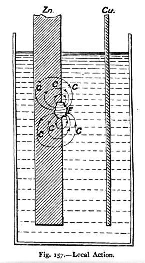
Local action from zinc impurities.
I've told you kids a thousand times ...
pickle in acid, dip in mercury ...
BEFORE you use the good new zinc electrodes!
* * *
So it's all about burning zinc !
... the platinum 'Grove' and cheaper carbon 'Bunsen' were relatively cheap and powerful for the early, leaky telegraph lines. Some battery advertisements today speak with derision about 'plain carbon batteries' ... but for early telegraph lines 'plain carbon' was better than 'platinum deluxe'.
But the problem was how to get rid of the gassy nitric acid reaction entirely ... or at least how to limit nitric acid's use to large central batteries where proper ventilation and supervision could be provided.
In historical interpretation, a premium is put on explaining 'the human experience' ...
Often these electricity generating systems were rapidly deployed across a wide geographical area without many workers (and supervisors) knowing anything about the underlying electrical theory or chemistry. The Grand Trunk telegraph rules of 1855 are full of commandments on how to save money by taking good care of the cell components. I couldn't find any health and safety precautions in the rules.
So, workers were routinely handling acids, breathing poisonous fumes, and handling mercury without much, or any, training on first aid measures or the long term consequences of their work. And this was an 'easy' white collar job compared to covering boilers with asbestos lagging, working in coal mines, making town gas out of coal, firing a steam locomotive, etc.
* * *
The Gravity Cell comes to the rescue ...

Zinc and copper gravity cell.
Free of toxic fumes, using relatively cheap copper and zinc, and a single diluted acid as an electrolyte, the one volt gravity cell was not as powerful as the two volt Grove ... but it was easier to maintain and well suited to local station circuits.
The Wonder of the Gravity Cell

Gravity cell, colourless top, blue at bottom.
The gravity battery came into use around 1850 ...
The copper electrode was placed in the bottom of the cell's glass tumbler, and copper sulphate crystals (toilet sanitizer blue in colour) were arranged around it. The copper's wire lead was insulated so it did not come into contact with the cell contents. The crystals used were to be smaller than walnut size and larger than dust - presumably to present a good exposed surface area available for aqueous solution. Clean rainwater was then used to fill up the tumbler above the level of the zinc 'crowfoot' at the top.
Next a little sulphuric acid was added to the water and the terminals of the cell were deliberately short-circuited to start the cell's chemical reaction.
When operating, zinc sulphate solution forms around the zinc element ... and copper sulphate solution forms around the copper element. The specific gravity of the copper solution is higher so a blue layer of copper sulphate solution forms in the bottom half of the cell - this is not a portable battery!
Zinc is 'consumed' as it passes into solution. The busy little ions in solution eventually cause dissolved copper sulphate to electroplate as elemental copper onto the copper electrode. When the cell needs renewal, the copper mass is removed for factory reprocessing and most of the zinc element has disappeared into solution.
However, if current has not been flowing through the cell ... copper gets up to the zinc level and deposits as CuO on the zinc - a black mud which fouls the battery and its ability to produce current.
The battery oil is a high viscosity mineral oil to prevent zinc crystals from creeping over the sides of the battery tumbler and only a fraction of an inch is needed to seal the top surface.
As the battery was used, zinc solution could be siphoned out and replaced with rainwater. Going 'by the book' the copper was not to be replenished by dropping copper sulphate crystals in from the top (and I'm sure that never happened, even on a bright, sunny Saturday afternoon!) ... When the original charge of copper sulphate crystals was gone, it was time to clean out the tumbler and renew the battery, according to 'the book'.
A 1913 textbook states that the gravity battery would last 5-8 weeks in a local station circuit ... or 2 months on a mainline circuit.
* * *
From a 1914 American text on telephony and telegraphy
... here is a partial list of the primary cells devised to that point.
'Primary' cells (e.g. Grove, gravity) PRODUCED electricity ... until their electrodes were consumed.
'Secondary' cells STORED electricity generated outside the cell (e.g. by thermal or hydro generation).
With major North American urban areas developing and possessing electricity and telephone systems by 1914, lead batteries were the preferred secondary (rechargeable) cells for urban communications circuits.
Below, the Grove and Bunsen cell specifications are shown together.
The gravity cell is a version of the Daniell cell.
The Daniell is shown near the bottom of this list.

List of century-old primary cell specifications.
* * *
Getting the telegraph signals down the line ...
science, people and experience ...

TBQ - dipping telephone poles in coal tar.
Sixty or seventy years into the telegraph era, these gentlemen are having a Tarbeque. In the early 1900s in the US, telephone poles are being field-dipped in creosote - coal tar. Note that the pole just removed is not perfect and tapered like today's. It does have a peak shaped into its top to shed the rain - oh, the craftsmanship of the good old days, eh?
Way back in the 1850s and 1860s - as you may have heard - most people knew very little about electricity, conductors, insulators, magnetism and of course even our high school chemistry was not known to them ... simply because most had never even SEEN a 'high school'.
Rural one-room schoolhouses were the education institutions attended by most Canadians up to the early 1900s. So much for having a limo at your prom ...
* * *
Intelligence and skills appropriate to different historical periods ...
WE ... know how to ... make and post a video of ourselves on the internet ... drive in the rain on a busy freeway around transport trucks.
THEY ... knew how to ... identify a tree by its common name and fell it with an axe, harness and plow with a horse, season firewood, make bread, and pickle the products of their gardens for the winter.
* * *
Generally, workers in 1860 knew as much about building a telegraph wire line ... as we did about setting up a local area computer network in the late 1980s. It was just very new technology - no one had ever built outdoor electrical wire lines before.
A few pointy-headed gurus knew many of the theoretical details ... while others with actual people skills were busily promoting the telegraph 'concept' to politicians and investors.
A telegraph wire line is not sheltered from the effects of the elements and natural forces like a pampered room-temperature computer network.
Even with all of our educational background today ... and without peeking on the internet ... can WE predict exactly how and when solar radiation cycles will affect a telegraph line during the next 5 years ?
... a lot was learned from trial and error.
* * *
What they learned ... often the hard way ...
- Wires stapled to living trees make very bad telegraph lines ... water and sap drain off the current before it travels anywhere.
- When cutting trees for poles, they should be cut in the winter when the sap is out. They should be debarked, and DRY before they are used. Otherwise ... water will get in, current will drain off, AND your poles will quickly rot out and fall over.
- The flow of electrical signals is not slowed by slack wires which dip between poles.
- Bi-metallic wire (e.g. copper-covered iron) deteriorates quickly out in the elements.
- Copper wire can stretch, iron wire can rust, either can break. Finding the right conductor and the right gauge of wire to use is a difficult problem.
- You must brace a pole line on a curve.
- Telegraph lines don't work well if you run them through railway tunnels.
- Whenever possible run the telegraph wires along a rail line or a road because it is too difficult to negotiate with all the landowners if you install them cross-country.
- Some materials such as ceramics or glass as 'insulators' help the signals flow farther down the wire.
- Some people like to shoot at insulators or throw rocks at them ... some people believe telegraph lines hurt their crops and livestock.
- Lightning can come into a railway station building and destroy the telegraph instruments.
- Rain or moisture in the air can interfere with the strength of telegraph signals. In particular, a line of wet insulators and poles can draw some current into the ground (a path of lower resistance) so little is left to flow through the wires.
- If wires have too much slack - so they won't break ... wind can blow the bare conductors into contact with each other and 'we can get our wires crossed'.
That is just a sampling of the problems they solved with experience and some scientific trouble-shooting.
As telegraphs were the first commercial use of electricity ...
This was the first time humans had strung electrical conductors across an expanse of land.
* * *

Position of brackets for 2 wire pole line.
These images are circa 1900.
For supporting just a couple of lines ... wooden brackets with insulators worked OK.
Everything was within easy reach of a pole-climbing maintainer.

Typical railway telegraph pole cross arm configuration.
Although the cost of telegraph line construction was negligible, compared to a railway line ... lines had to be surveyed ... poles had to be placed and holes dug for them ... arms and insulator pegs had to be attached ...
Getting the wire tension and pole bracing right was an important step ... the inspecting railway bosses would not want to see some poles leaning toward the tracks and some leaning away !
There were many other details which went into a good telegraph line. Perpetual maintenance was critical for this essential railway communications system.

Iron and copper wire - methods for attaching to insulators.
As you can see, the main line did not go around the insulators ... it just grazed them.
There were different techniques used when securing copper or iron lines.

Early CPR stonewear/porcelain insulator.
I purchased this nice old insulator in western Canada, I think. It probably had a long and undisturbed career on a sleepy branchline until the railway line was ripped up. Or it was never used at all.
I don't know if it is properly 'stoneware' or 'porcelain' ... but you get the idea ... a glass-ceramic material. Instead of stamping 'CPR' into the ceramic material, it was glazed on. A thread to match the threaded peg of the railway telegraph arm is visible deep inside the insulator when its 'bell' shape is viewed from below.
With a conducting wire attached, and even if the insulator was wet ... there was a long distance for a fugitive signal current to travel to contact the wooden peg - up and deep inside the dry bell.

Two wire telegraph line at CPR Last Spike (1885).
The CPR 'Last Spike' as celebrated by the workers at Craigellachie B.C. after the official party was finished.
You can see the high-quality two-wire telegraph line which has been strung for this section of the new transcontinental line.

CNR glass insulator on threaded, treated 'pin'.
Later on, glass insulators were used - this one has a CNR badge. These were probably cheaper, but not as efficient insulators as the white ceramic above ... because they apparently maintain a thin film of water molecules on their surface.
By this time, powerful secondary lead cells were probably ramming the current through the wires ...
so high efficiency insulation was probably not as critical for the main telegraph line.
The internal thread is visible. The insulator is attached to the treated wooden threaded peg which would be driven into the crossarms.

CNR insulator - closeup of flaws.
Looking more closely, you can see weathering on the wooden peg and perhaps condemnable flaws in the insulator. Vertical cracks near the insulator's base can hold water which can help current leak from the signal wire placed in the groove. You can see scarring of the glass at the groove where the main line wire was tightly held by the wire tie.
* * *
Other cool features of a telegraph line ...

Telegraph wire arrangement for line testing.
Whether it was crossed or broken wires, broken poles, brushing by branches, or various ground faults ... telegraph linemen, particularly when telegraph technology was new, had to be patient trouble-shooters.
First a particular station would report problems with their signal and, starting with that station's wires ... and by process of elimination ... the maintainer would have to narrow his search to smaller and smaller segments of line until the problem was found.
(It was probably a common practice to have spare lines available on high traffic routes. This would enable telegraph traffic to continue - while the the defect was being isolated and repaired on the line taken out of service for repair.)
By undoing the wing nut in the image above, the maintainer could break the continuity of a telegraph line without the physical difficulty - and structural consequences to the line (PING! ... wire-ends fall down into the snow) - of making a fresh cut in it.
Both segments - could be tested separately to further isolate the problem.
* * *

Line tapping clamp for remote telegraphy in emergency.
At a wreck, a telegraph operator could communicate directly from the location - from anywhere along the line !
The telegraph operator would be relaying instructions for resources from the company official in charge of cleaning up the wreck. Headquarters would also be keen to know exactly when the line would be in service again as trains would be backing up all along the system.
As with the Test Connection above, a telegraph conductor must be completely severed ... so that a telegraph key can be put into the circuit (in series) to both send and receive. As usual, the key must bridge and break the circuit to send signals.
If a telegraph key and sounder/relay is simply clipped 'in parallel' to an intact wire ... the current will take the path of least resistance through the intact wire and 'ignore' the sending and receiving equipment.
How I think this clamp works ...
(see image below)
The main clamp casting is insulated down the middle (darker segment).
- Unscrew the thumbscrew of the 'CLIP' and remove it. Notice how the clip (white in the diagram) jumps (conducts) over the insulated segment.
- Raise the clamp under the wire to be used until the wire sits in the longitudinal groove into which the 'main line wire' thumbscrews turn. The cable is under tension so the screws must be firmly tightened before cutting.
- Saw through the wire at the break point marked ... and ensure the two cut ends do not touch.
- Insert your send/receive instrument's (e.g. telegraph key) wires from below into the holes into which the smaller thumbscrews turn and tighten.
- You are ready to telegraph from the site! The main line wire's current (for example) will arrive at LEFT and drop to your key through the LEFT key wire. After passing through your key, the current will rise from your key up the RIGHT key wire and continue out the RIGHT side on the main line wire.
- When field use of the telegraph line is complete. Disconnect your send/receive instrument's (key) wires.
- Replace the CLIP to restore the continuity of the line and leave the clamp connected ... a maintainer will later splice the line.

Speculative method of using emergency line tapping clamp.
Oh. Come. On !! ...
In an real emergency, even a line tapping clamp and a telegraph key were not needed to send. The line (circuit) could be cut. Then the two ends could be tapped together to send a Morse message (or bridged with scrap wire if they were pulled apart by wire line tension).
If necessary to receive a response, it might be possible to see arcing between the ends.
Or ... a tongue or other sensitive wet human 'bridge' could be used to feel the signalled response !!
(This was 'anecdotal' in one textbook.)
... Only in an emergency in the wilderness would you do something like this !
Once powerful secondary batteries were pumping more power through the lines - thankfully - appropriate emergency procedures were probably prescribed which would NOT involve the 'tongue relay and sounder'.
The underlying point is ... this was simple, elegant technology which worked well in the wilderness.
* * *

Installing a telephone pole line by horse circa 1900.
Fifty years after the Grand Trunk Railway's telegraph line was built, this is how telephone lines were installed across country circa 1900 - a US photo. The supply reel of shiny new wire is on one end, and the horse powering the work is on the other end. The fastening to insulators and correct tensioning of the wires required skill and experience.
As stated earlier, telegraph was the first commercial use of electricity. Metal wire pole lines had never been constructed before this.
Power lines, telephone lines, cable television lines, etc. all came after the telegraph.
Preview of
Telegraph Part 5
Simplified local station circuit and instruments ...

- In this simplified conceptual sketch you can see that the main line wires (solid lines) work through the relay and key.
- The relay has a special light, spring-returned 'armature' D which is very sensitive to the weak signal coming from the main line. R represents the solenoid which attracts the armature.
- The relay (through a mechanism which is not shown) translates the physical motion of the light armature D to a conductor (not shown) which makes and breaks the circuit between the two terminals labelled W.
- The dotted line represents the separate local station circuit with its small gravity cell (local battery). The relay physically energizes or de-energizes (W-W or W W) the relatively strong local circuit to actuate the sounder.
* * *
Simplified conceptual sketch of the main telegraph line between cities.
I have substituted Grand Trunk Railway cities ...

- Montreal and Toronto have BIG primary batteries putting electromotive potential into the main telegraph line at both ends.
- Notice that polarity is maintained through the entire circuit from ground to ground.
- At Kingston, contacts 1 and 2 must be bridged so Montreal and Toronto (and everyone in between) can send to each other.
- Contacts 1 and 2 should be connected to a lightning protector to save the local instruments.
- The local circuit has its own local gravity battery and an available ground which may be connected to diagnose line problems.
Interesting details about the instruments and local circuit will be covered in Telegraph Part 5.
* * *
Before Canadian Confederation
low barriers to entry allowed telegraph companies to rapidly spread their networks.
It seems their target market was business communications.

Provincial Telegraph Co advertisement.
* * *
After Canadian Confederation ... here, circa 1871
telegraph systems were important businesses.
Hugh Allan - of the Allan shipping line.
Andrew Allan - his younger brother.
Peter Redpath - son of John Redpath (sugar magnate).
Sir William Logan - noted geologist - established Geological Survey of Canada.
Dr. George Campbell - surgeon; Dean, McGill Medical Faculty; corporate director & investor.

* * *

At Glacier House BC circa 1910.
Photographers hate telegraph poles!
At Glacier House BC, circa 1910, the necessary technique of bracing telegraph lines on curves is illustrated.
Removed from this photo during colourizing was a tall telegraph pole standing behind the locomotive ... this 'offender' is visible on other photographs and postcards.
Telegraph lines generally entered the rear of stations
and the second pole from the camera sends the lines over the tracks to the missing pole.
If only the postcard artists understood the importance of the telegraph to Canadian wilderness railroading !