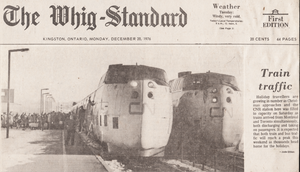
This post looks at the PT-6 series of engines. A power plant of this family was used on CNR's Turbo train. As you already know, there was a fair amount of public/private partnership in this story.
I found an unexpected link between the Turbo train references and other books I have about technology. The person named below is key in interpreting the engine at the heart of the Turbo.
I found an unexpected link between the Turbo train references and other books I have about technology. The person named below is key in interpreting the engine at the heart of the Turbo.
 |
| from: Flight International; Oct 9, 1969. |
Howard Fowler wrote two books for what was then known as the National Aviation Museum - one on aircraft piston engines and one on jets. They were written 30 years after the events reported above.
The text below is from: The Evolution of the Jet Engine; Howard S Fowler; 1999; National Aviation Museum, Ottawa.
'It is interesting to compare the two versions of a seven-passenger light aircraft, the de Havilland Beaver, which was powered by a Pratt & Whitney R 985 Wasp Junior air-cooled radial engine, and the Turbo-Beaver which was essentially the same aircraft but powered by the PT6-A6.
'The Wasp engine, of 450 hp, weighed 309 kg, while the PT6-A6 developed 578 hp, for a weight of only 131 kg. It is stated that the 'length of the cabin is increased by 2 1/2 feet, giving space for two more passenger seats. This, and the 12% increase in cruising speed, results in an improvement of 35% in operating economy'. The take-off distance is decreased from 381 to 274 metres, giving a considerable advantage in short-field ability.
'The PT-6 had a most interesting history of development. The first engine was run on the testbed in November 1959, flew in May of 1961, and was certified in 1963. It began by producing 475 shaft horse power, and the series was ultimately developed up to 1350 shp. A most ingenious layout resulted in an overall diameter of only 48 cm, a total length of 152 cm, and a frontal area of 0.18 square metres. [The figure farther below] shows how this was achieved, albeit at the expense of a somewhat contorted airflow path through the engine.
' ... There was a long series of PT-6 engines, in which continual development of compressor stages, of the turbine, and of fuel and control systems, raised the power output [as noted above].
' ... Ultimately it was decided to redesign the engine, as the PT-7, embodying all the lessons learned in the PT-6 series.
' ... The flow path was straightened out, and a nose intake capable of rejecting ice particles and other foreign matter was developed during the extensive testing in the National Research Council (NRC) icing tunnel.
' ... In the 1960s, the writer [Howard S Fowler] was asked by Dr MacPhail, his Director in the Mechanical Engineering Division of NRC, to look into the real flow in the channels of the impeller. Using data supplied by Pratt & Whitney, a ten-times full size model of the PT6 impeller was built and spun at 70 rpm, with the writer firmly fixed into its centre, and the actual flow was mapped using smoke streamers and a hot-wire anemometer. Some 200 hours of running and many more of analysis, revealed the true picture of the flow in the impeller ...
' ... This information was passed to Pratt & Whitney, whose aerodynamacists were then able to develop a greatly advanced mathematical treatment of the true flow, which enabled them to design a compressor with a predictable performance far in advance of previous machines.'
* * *
Jet versus Prop-jet
The critical difference from the jet, is that energy is focused on turning that central shaft to turn the propeller.
Like the Turbo train application, the compressor turbine operates continuously during idling, BUT the power turbine (here for the propeller) is only engaged when needed for vehicle propulsion.
* * *
In these two schematic diagrams, the white arrows represents the relative energy flows. The black arrows represent the torsional force imparted to the central shaft. The general air flow through both engines is from left to right.
First, looking at the pure jet engine: The top big white arrow represents the energy input of fuel. The fuel is aerosolized and ignited and the expanding gases (arrow pointing right) turn a turbine (vertical hatching). The torsional force is transferred 'upwind' by the shaft (notice the white curved energy arrow underneath). Near the inlet, this torsion drives the compressing turbine (vertical hatching). Compressing air causes it to heat up, and it also increases the amount of oxygen available (in a given volume of air) to support fuel combustion.
When the jet is ready for work: hot, oxygen-rich intake air is mixing efficiently with the fuel aerosol in the fuel burners. The tailend turbine is designed to steal just enough energy from the expanding gases to spin the compressor. The propulsion for the aircraft comes from the thrust out the tailend - the big white arrow at the right.
 |
| from: The Evolution of the Jet Engine; Howard S Fowler; 1999; National Aviation Museum, Ottawa |
Now looking at the prop-jet engine schematic (above), the fuel/energy input is again represented at the top. There are two separate turbines at the tailend with concentric shafts: one shaft operates the compressor at the upwind end, the other turbine spins the propeller. The hot combustion gases exit the rear of the engine and provide some thrust.
The critical difference from the jet, is that energy is focused on turning that central shaft to turn the propeller.
Like the Turbo train application, the compressor turbine operates continuously during idling, BUT the power turbine (here for the propeller) is only engaged when needed for vehicle propulsion.
* * *
 |
| from: The Evolution of the Jet Engine; Howard S Fowler; 1999; National Aviation Museum, Ottawa. |
With the Turbo train's PT6 in an aircraft application (e.g. a Turbo-Beaver), there is no thrust out the tailend. As Howard Fowler noted, the air flow is relatively circuitous; the tailend of the engine is located at the cockpit firewall.
Similar to the prop-jet diagram, you can see that the compressor turbine is separate from the power turbine. The compressor turbine turns during idling with the power turbine engaged only when vehicle movement is desired.
Similar to the prop-jet diagram, you can see that the compressor turbine is separate from the power turbine. The compressor turbine turns during idling with the power turbine engaged only when vehicle movement is desired.
* * *
 |
| from: Turbo-propulsion; W G Blevins; Canadian Rail Feb 1969; Canadian Railroad Historical Association. Collection of LC Gagnon. |
In the Canadian Rail Turbo train illustration above, you can pick out the segments of the engine.
Below, in an aviation application, you can see the engine again.
* * *
* * *
Rhetorical Corner:
Turbine engines in railway service are not used to lift the vehicle off the rails.
Is it therefore necessary for the turbine engine itself to be as light as possible?
* * *
Below, in an aviation application, you can see the engine again.
* * *
 |
| from: The de Havilland Canada Story; Fred W Hotson; 1983; Canav Books. |
Above, is the PT6 turbine engine installed in a Series 300 Twin Otter aircraft.
16 is a PT6A-27, free-turbine powerplant producing 620 shaft horsepower. 17 are two engine exhaust nozzles. 14 is the air intake deflector. 12 is the air flow duct. 18 is the engine air inlet.
* * *
 |
| from: Overland Models advertisement; Locomotive & Railway Preservation; May-June 1991. |
Turbine engines in railway service are not used to lift the vehicle off the rails.
Is it therefore necessary for the turbine engine itself to be as light as possible?
* * *
My father included this article in his Turbo train file.

On April 27, 1967, (this is based on an apocryphal story later published in the Montreal Gazette) Prime Minister Lester Pearson did not travel from Ottawa to Montreal aboard the CN's Turbo train to open Expo 67. This did not happen because the Turbo train was not ready by the date which had been advertised and promoted.
Over a year later - on September 14, 1968 - this cover story ran in the Weekend Magazine. This newsprint magazine and the comics section were included with the Saturday edition of many Canadian newspapers of that era. Near the end of the article is this passage:
" ST6 engines will whisk Canadian National's plane-type aluminum turbotrains ... "
... So, as this article was being printed, neither was Canada's current leader, Prime Minister Pierre Trudeau, going to be riding the Turbo.
The first image below is the initial two-page spread of the article - to show you the presentation. The text is removed and reproduced below in a more readable size.
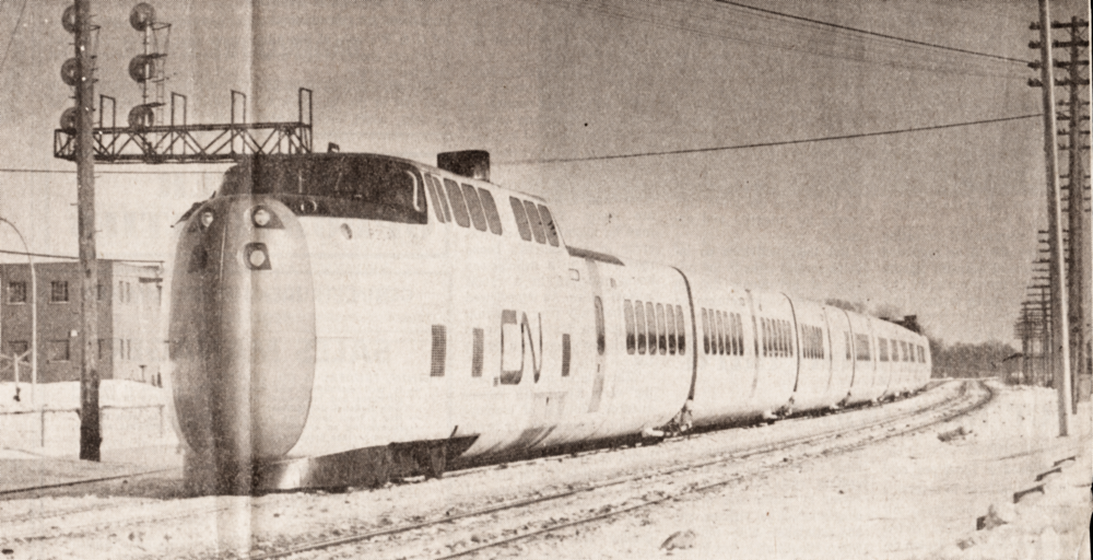
Below, the Turbo train is (probably) seen approaching Kingston from the east at around mile 171. For a number of years, in regular service, its zone speed would be 95 mph, but it would have to slow to 40 mph to operate through the horseshoe curve at Kingston's 'outer' station - the curve being virtually unchanged since it was laid out by the Grand Trunk Railway in the 1850s.
In hindsight, the 'unspoiled' heritage roadbed and public crossing timing circuits would limit the Turbo's speed more than wind resistance or the absolute weight of the trainset and its power plant.
Perhaps this story idea was advanced by the Turbo partners at this point because of the delays in bringing the Turbo into revenue service - a case of 'earned media' to help take a little pressure off the government-owned CNR as well as its private contractor, United Aircraft.
Below, the Turbo train is (probably) seen approaching Kingston from the east at around mile 171. For a number of years, in regular service, its zone speed would be 95 mph, but it would have to slow to 40 mph to operate through the horseshoe curve at Kingston's 'outer' station - the curve being virtually unchanged since it was laid out by the Grand Trunk Railway in the 1850s.
In hindsight, the 'unspoiled' heritage roadbed and public crossing timing circuits would limit the Turbo's speed more than wind resistance or the absolute weight of the trainset and its power plant.
Perhaps this story idea was advanced by the Turbo partners at this point because of the delays in bringing the Turbo into revenue service - a case of 'earned media' to help take a little pressure off the government-owned CNR as well as its private contractor, United Aircraft.


* * *
In early 1966, a Canadian Rail article presented some early images of the arrangement of the turbines. This section will wrap up this post on the Turbo's power plant.
 |
| from: Turbine Motor Trains; Michael Leduc; Canadian Rail, April 1966; CRHA. Collection of LC Gagnon. |
For motive power, I understand that two turbines were placed in each power car. Here, also, is the power transmission arrangement as it was foreseen in 1966.
Only the American version of the Turbo, which would be under test primarily in the north-eastern US, needed the capacity to operate using a DC motor taking power from a third rail. As you know, particularly around New York City, the turbines could not have been operated in tunnels and other enclosed areas where a third rail power system had been established for safety reasons.
Jumping to a conclusion, the darkest of the THREE turbines on this unit is probably the trainset's fifth turbine - which would act just like an airliner's auxiliary power unit to provide 'hotel power'. The motive power turbine located closest to that APU is probably the one designated as its backup. If the APU turbine failed, it could be replaced in its function of powering climate control and lighting by switching over a designated turbine from propulsion to APU duties.
 |
| from: Turbine Motor Trains; Michael Leduc; Canadian Rail, April 1966; CRHA. Collection of LC Gagnon. |
The latter ran up through the large partition between the passenger dome chairs.
You can see how blowing snow and road dirt could foul the turbines if intake air filtering wasn't highly efficient.