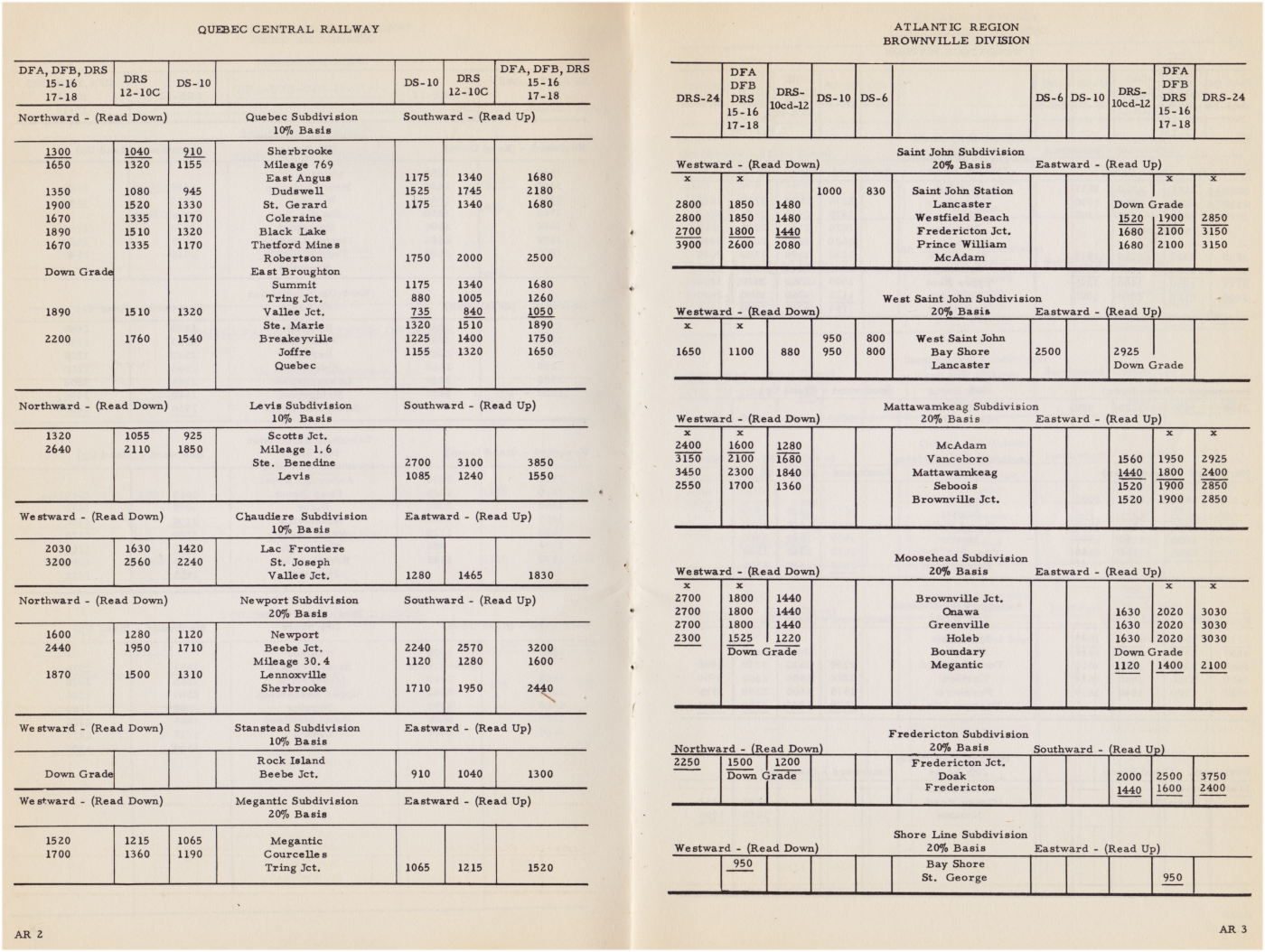
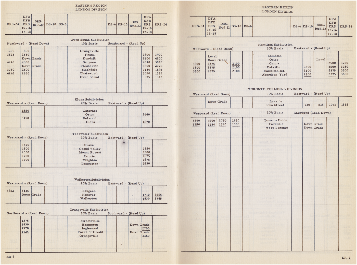
This post looks at the criteria for matching available locomotives to a given train (or vice versa) back in 1962. While computers would perform this work today, this booklet presents a method for using a pencil for the task.
It is tempting to interpret the process involved, but the booklet explains the steps plainly. Key components behind the calculation are:
- Car tare and car content weight.
- Subdivision gradient values, especially the ruling grade (expressed in equivalent tons).
- Condition of the rail (generally 'weather on the rail').
* Throughout the booklet the 4-digit numerical ratings
(what a unit can pull, what power is required for a segment of line)
are based on 'equivalent tons'.
* * *
Not Included
The booklet does not consider particular cold weather phenomena including the ability to pump air through a trainline to fully charge it and release the brakes. Trains would sometimes be shortened to try to correct this. Obviously, this phenomenon would be independent of tonnage.
... Nor does it consider the additional power needed to overcome the increased viscosity of cold journal box oil when starting a train.
Steam Era Problem-Solving
The classic steam locomotive tactic of reversing to bunch coupler slack - in other words to start the train 'one car at a time' - would have been familiar to engineers in 1962. Almost all engineers of this era would have started their careers on steam.
As well, the time-consuming necessity of doubling a hill would be a employed when an engine lacked the ability to pull a train up a grade.
Steps:
- Arrange any necessary protection for the rear of the train.
- Inform the dispatcher of the delay at the earliest opportunity.
- Secure the tail end of the train from movement.
- Run the front end of the train to the top of the offending grade and secure it in a siding.
- Arrange protection for the headend of the train.
- Reverse the engine to the tailend of the train.
- Call in the tailend flagman, if applicable. Burning fusee(s) would be left for protection.
- Run the tailend up the hill to the siding.
- Reassemble the train and (usually) clear in the siding.
- Call in the flagman protecting the headend of the train. (Fusee, etc)
- Be governed by the dispatcher's instructions ... now that your train's unexpected delay has given his 'chess board' a good shake. Until more important, delayed traffic gets by, you might have some spare time to enjoy in a picturesque woodland area! (Depending on the circumstances, the train might be able to continue under normal timetable and train order processes).
In his early days as a steam era fireman, if locomotive sanders were inoperative or exhausted, Rolly was sometimes directed to walk alongside the power and throw any available trackside grit under the drivers.
In 1977, at the White River, Ontario yard office a similar book was still available for use. If it was necessary to assemble a local freight or a wayfreight there, yard office staff would perform the calculations before turning the switchlist/train consist over to the running trades crew ordered for the train.
In 1977, the 10%, 20%, 30% basis system shown below was used to help calculate 'wheelage' or train resistance. Grade, then curvature (with flanges binding on rails) are usually the key 'drags' on what a given power consist can pull.
Wheel tread to surface friction is a much bigger drag on traction for rubber-tired road vehicles than it is for railway equipment. Stopping a railed vehicle quickly 'feels' like locking a car's brakes on glare ice.
Wheel tread to surface friction is a much bigger drag on traction for rubber-tired road vehicles than it is for railway equipment. Stopping a railed vehicle quickly 'feels' like locking a car's brakes on glare ice.
The CPR worked to replace the diesel manufacturers' model letters and numbers (a modern-ish example: SD40-2) with a company system, in which letters had the following general meanings. Most of you are already conversant with this system.
S - switcher
Low horsepower - usually only suitable for yard switching, sometimes without MU capability.
RS - road switcher
More powerful than a switcher and often used in multiple unit control (MU) configuration to pull trains. Often, the engineer could keep his head in the cab to observe hand or lantern signals during switching - through forward and rear-facing windows. These signals were often relayed (including from car roofwalks) by crew when the coupling location could not be seen directly. Radios were not commonly used by Canadian railways in 1962.
P - passenger
F - freight
A - usually a 'carbody' unit with a control cab (e.g. the 1800, seen below)
B - usually a 'carbody' unit without a control cab
H - hydraulic (transmission)
As you also probably realize: 15, 16, 17, 18, etc refers to unit horsepower in hundreds.
As you also probably realize: 15, 16, 17, 18, etc refers to unit horsepower in hundreds.
Locomotive images appearing below were collected by my father.
For the purposes of 'decoding' much of what the CPR was running in 1962, below, is a handy list
of units used (extinct on CPR by 1984) from the Trackside Guide 1984 - Bytown Railway Society.
The Road Numbers column (above), can be cross-referenced to the Final/Previous Number(s) columns (below).
 |
| LC Gagnon clipping, 1955, probably from Trains magazine. |
 |
| CPR photo obtained by LC Gagnon. |
Eastern Region
Dried sand is being loaded into the unit's sanding reservoir, above.
 |
| Canadian Pacific Spanner, January 1950. |
* * *
Meanwhile on the CNR ...
At the same time in history - immediately after the complete elimination of steam locomotives - the CNR was publishing their diesel tonnage ratings in their employee timetables. Two facing pages are presented as a single image below. They come from this employee timetable.


